
In the last part, I wrote about the first steps of building my own FFBeast Force Feedback Joystick. If you have not read the first article yet, I’d recommend to do this first. You can find it: here.
In this article, I’ll walk you through my part choices, modifications, hiccups, and overall experience building the joystick. If you’re planning to build the FFBeast yourself, this article can give you a good overview of what to expect and help you be aware of potential challenges.
Step 1: Ordering the parts
The first task was to order all the required parts from all the different suppliers. There is a list on the FFBeast website with the BOM (Bill of material), listing all the parts that you need to order for your build. Most of the parts are of the shelf components you can buy on eBay, Aliexpress or maybe even your local hardware dealer.
All the screws and nuts were sourced from a German store with which I’ve already ordered several times and the prices are acceptable. More specialized hardware like gears, bearings were sourced from Aliexpress.
I chose not to 3d print the pulleys like it is instructed on the website and went with standard HTD-5M pulleys. For the gimbal side, I chose a 5M60T with an 8mm bore and a width of 16mm. A friend of mine helped me to cut the additional mounting holes on his milling machine. You could also use a drill press.
For the motor gear, I chose a 5M20T, also 16mm wide and with an 16mm bore to fit the shaft of the industrial servo motor, instead of the recommended motor.
Electronics
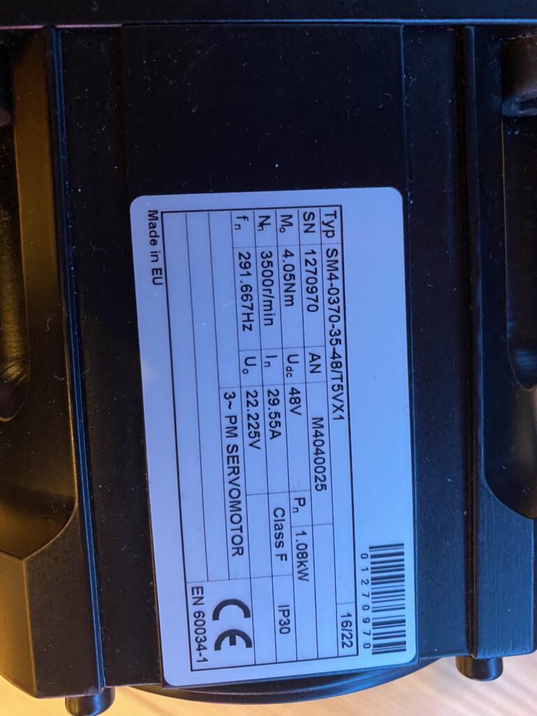
I decided to use an affordable 3-Phase Industrial Servo Motor with a rated output power of 1,08KW. The type number is SM4-0370-35-48/T5VX1. These seem to be rather uncommon and you cannot find much documentation or even a datasheet for this motor. However, since I was able to get them for around 50€ per unit, I decided to give them a try.
For the encoders, I went with the best recommended option: The AMT10E3-V. This encoder allows a resolution of up to 20480 CPR (Counts per rotation). Note that the datasheet states 5120 PPR (Pulses per rotation). This confused me at first. PPR and CPR are not the same. Every Quadrature decoder works by outputting two signals A and B. These signals consist out of a square wave with a 90 degrees phase shift.
When we are talking about PPR, we are only counting the pulse (combination of rising and falling edge) on signal A. When we look at CPR, we are counting all transitions from both signals A and B. Therefore CPR equals to PPR * 4. For the AMT10E3 this means 5120*4=20480 CPR (quadrature counts/rev).
The AMT10E3 is one of the more expensive component in this build, costing about 22€ a piece plus 20€ shipping to Germany but it is worth it comparing to lower resolution encoders. The increased resolutions moves the need for “smoothing” and the ODrive is able to more effectively counteract the cogging of the servo. This allows for a smother experience.
The complete joystick is controlled by an ODrive v3.6 clone from Aliexpress. If you want to spend some extra money, you can buy the original here. The clone did work out great for me. The ODrive 3.6 provide the two motor drivers needed for the pitch and roll axis and the interface for the joystick buttons.
Power
Providing enough power is essential. More power means greater force. Therefore, the most important part is the PSU (Power Supply Unit).
It needs to apply enough current to produce the required torque. Since the servos operate in stall-mode, the voltage is not important, as long as it allows enough current to flow. I’ve been using a 12V PSU with 48V volt motors without any issues so far. I tried 48V vs 12V on my bench PSU and did not notice any difference in force output.
I strongly recommend not to use any of those “LED Power supplies”. These are usually garbage and are unable to output the specified power without dropping the voltage. If you want a reliable and safe PSU, I would recommend to use a MeanWell PSU. You can also use old server ore notebook PSUs. It’s up to you.
In my case, I chose a MeanWell PSU that I had laying around from another project.
The specific type is: RSP-320-12. It is capable of delivering up to 26.7 Amps at 12V and therefore more than enough for the motors I am using at the moment, giving me some headroom to add stronger motors later on.
CNC Parts
Unfortunately, not all parts are lasered sheet metal. To mount my Thrustmaster Hotas grip, I need an adaptor. I tried 3d printing with PETG but it is not strong enough.
The only real solution here was to CNC it out of aluminium. Since I don’t have access to a lathe ore a mill,
I had to hire someone to do this for me. Nowadays this is an easy thing with a lot of companies offering CNC services. I played my order with JLCPCB. It is affordable but it will take some time. Therefore, you wont see the results in this article.
Lasercut Parts
The Laser cut parts were ordered from LTO, an affordable laser parts supplier in Germany. If you are not in a hurry, they are probably the cheapest option here. In my case, it took around 2 month after payment for my order to finally arrive. The overall quality is satisfactory and the pericision also good.
You have to pay close attention to the BOM while ordering your parts. Their minimum order value makes reordering small parts very expensive, not mentioning the additional waiting time.
Step 2: Unboxing the lasered parts & finding the first issue
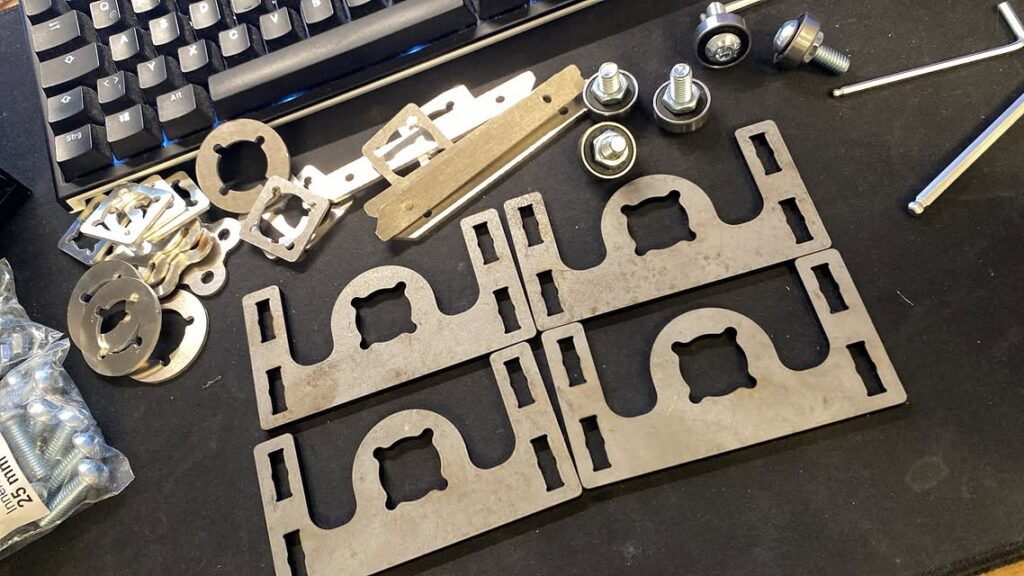
As the lasered parts arrived and I immediately started assembling the most complex part of the build: the gimbal core assembly.
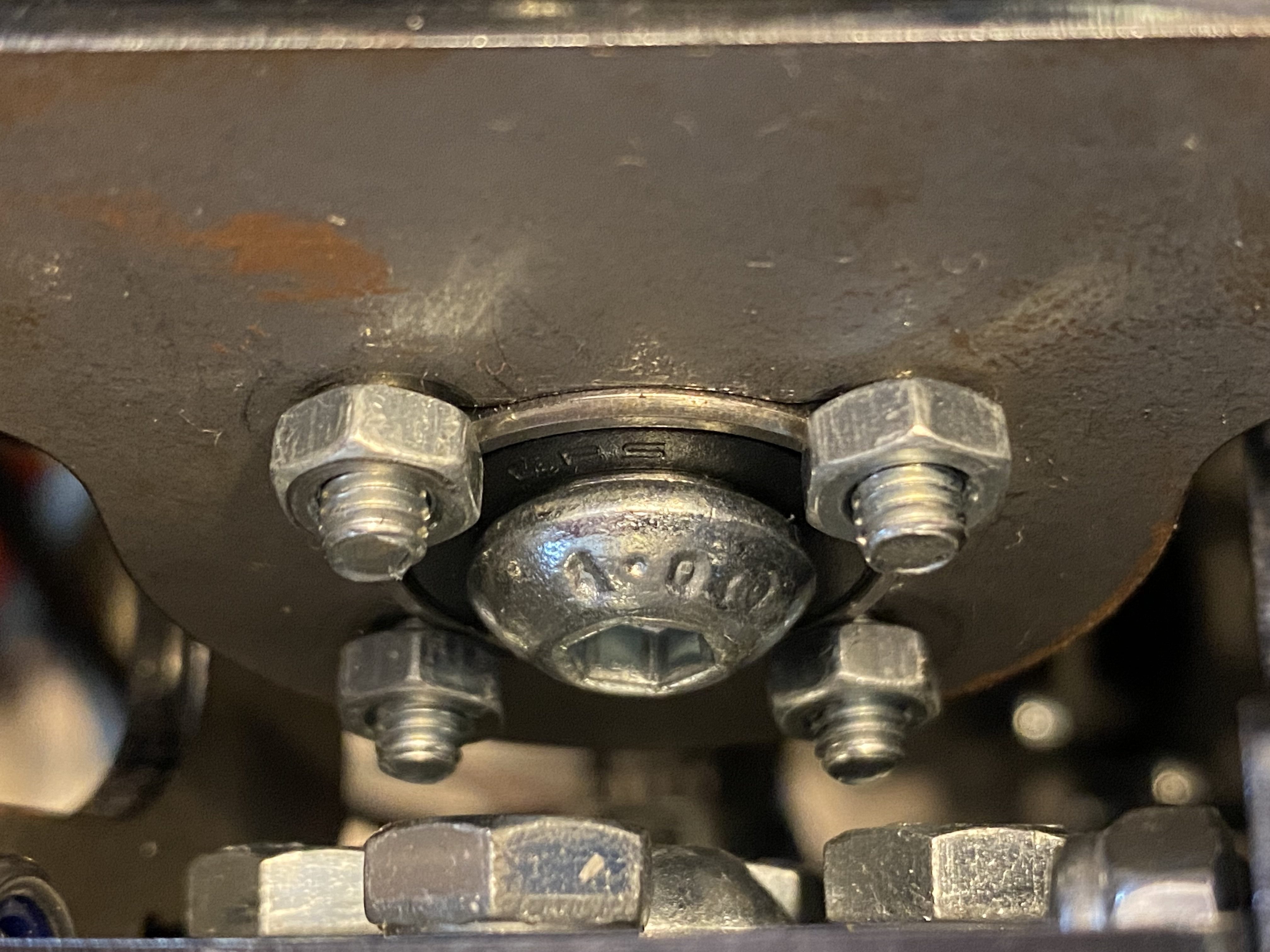
During assembly, I noticed that the bearings did not fit properly. They were 1 mm thicker than expected. I checked the order confirmation and the BOM to verify that I ordered the correct part. The thickness of the material matched the BOM.
When I double checked the CAD model, I noticed that the steel part was designed to be 5mm thick, however the BOM said 4mm. It took a while to figure out what went wrong.
Make sure to verify your BOM is correct before ordering
I initially started the Project back in June 2024. It was at this point that I bought the plans. I initially placed the order for the laser parts in June 2025. The CAD files and plans that I bought last year were Version 2.0. The current Version is 4.0. When I ordered the parts in June, I took the drawings from Version 2.0 but the Thickness/Amounts from Version 4.0.
This also meant, that I ordered some screws that I did not need and that I was missing some I did need. This added further delays and costs to the project. I would strongly recommend to double check, that your plans and the FFBeast BOM version match. Otherwise, contact the seller and ask for plans for your specific version or use the Internet Archive.
I also ended up designing a fix for the 1mm tolerance and placed an additional order. This added even more cost. For now, I 3D printed some spacers that work fine. I will however replace these with steel parts.
Preparing the gears
The last problem I had to fix were the gears that had to be attached to the gimbal itself. This requirde me to drill 4 correctly spaced holes in the gear to mount them. Since I also ordered only 30mm long M6 screws and I did not want to reorder the 35mm long variant and pay extra shipping, I decided to not drill 6mm holes but to add M6 threads to the gears. Fortunately a friend helped me out with his CNC. Again, this is not required and a drill press would have been good enough, if I had one.
The rest of the build went smoothly. I won’t go to much into detail here. This article is about my experience building it, not an instruction.
Assembling the gimbal is a bitty tricky at some points. You have to be very careful to assemble it in the correct order. Otherwise you wont be able to completely assemble it. You also have to make sure not to forget nuts and tighten the screws properly. You may use loctite to secure them. I had issues with screws unscrewing due to the vibrations.
Step 3: Wire up the electronics Pt.1 (ODrive)
Preparing the servos
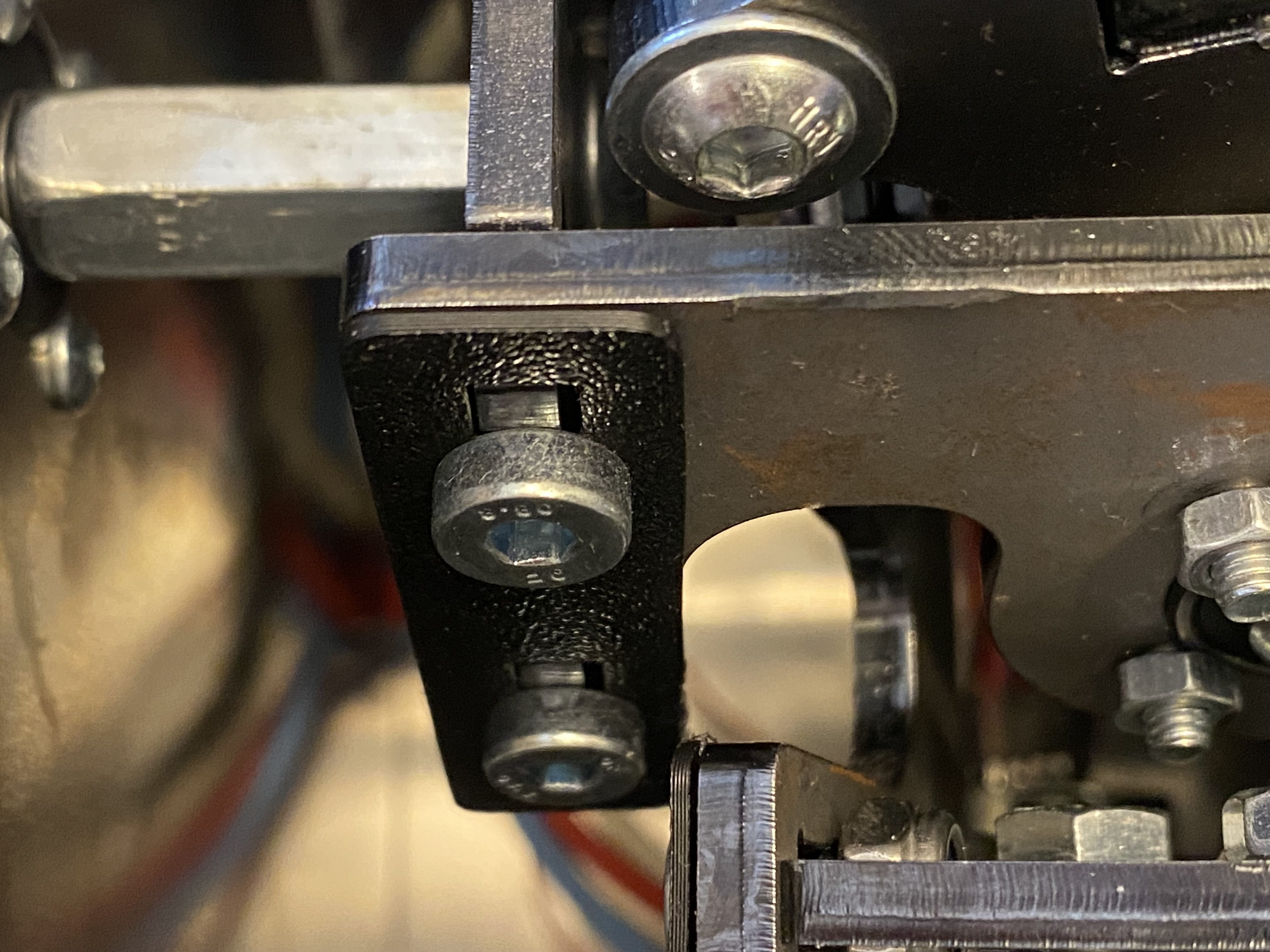
The electronics were a bit more straight forward. I decided to use Industrial Servo Motors. I mounted the ODrive to the redesigned side panel. At this point I ran into another issue. I redesigned the sliding part of the side panel to fit the servo motor but forgot to also increase the cutout of the side panel itself. Lucky as I am, it barely fit. If you want to use a bigger motor with my redesigned slider, you also have to change the side panel itself.
For the encoders, I designed a custom mount that attaches to the inner side of the slider. A coupling was pressed onto the shaft, connecting the motor shaft to the encoder.
Wiring the ODrive
Next up was wiring up the ODrive itself. I started by attaching the power cables. Because the PSU will be directly mounted to the case, I omitted installing any disconnects on the power line.
To reduce the voltage drop across the supply wires, I decided to use 6mm2 wire. 4mm2 wire would have been sufficient for 26A. However, more is always better and it provides enough headroom for future expansion or bigger motors! Since the wires are close to the sharp edge of the panel cutout, cloth tape is used to protect the insulation from being damaged and to prevent a short.
Attatching the braking resistor
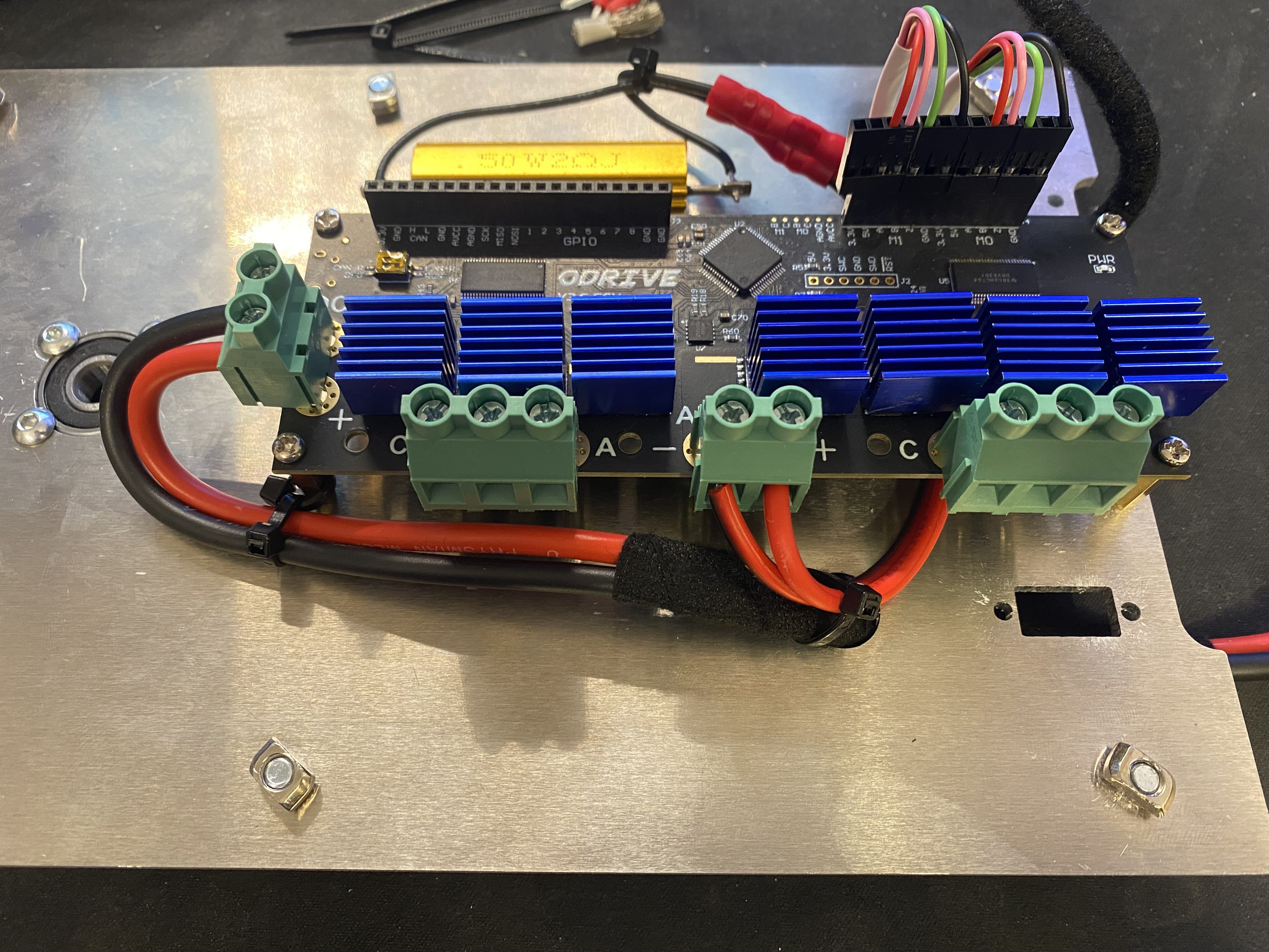
The ODrive comes with an braking resistor that dissipates additional power into heat. It is mounted to the panel with thermal paste glue which allows for better heat dissipation and mitigates the drilling of additional mounting holes.
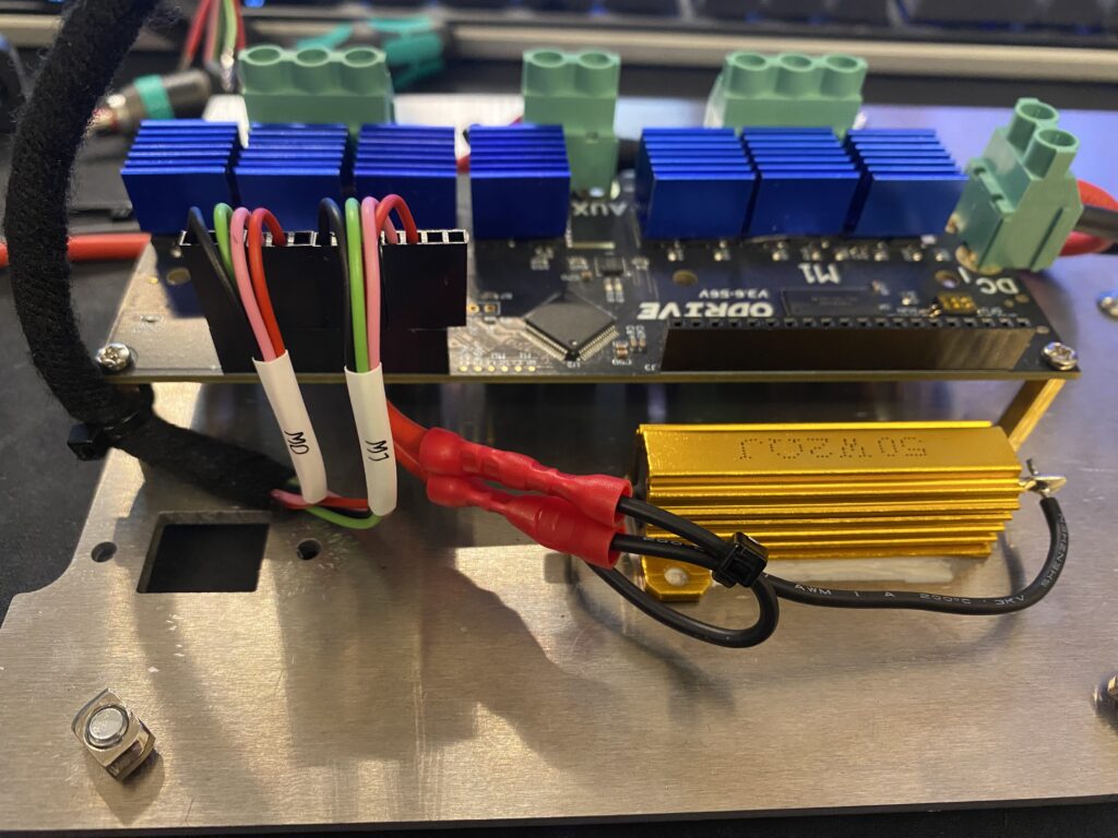
In this picture you can see the braking resistor. Since the preinstalled wires were too short, I extended them using crimp connectors.
Additional wire looms
I made a custom wire loom for the encoders and labeled them with heatshrink labels. A second loom for the joystick buttons will later be added. I crimped dupont connectors to the wires and used cloth tape again to create a neat loom that also protect the cables from physical damage. I did not have the right dupont connectors on hand so I had to use larger ones. This however is only a cosmetic issue. I’ve already ordered the correct ones and will replace them later.
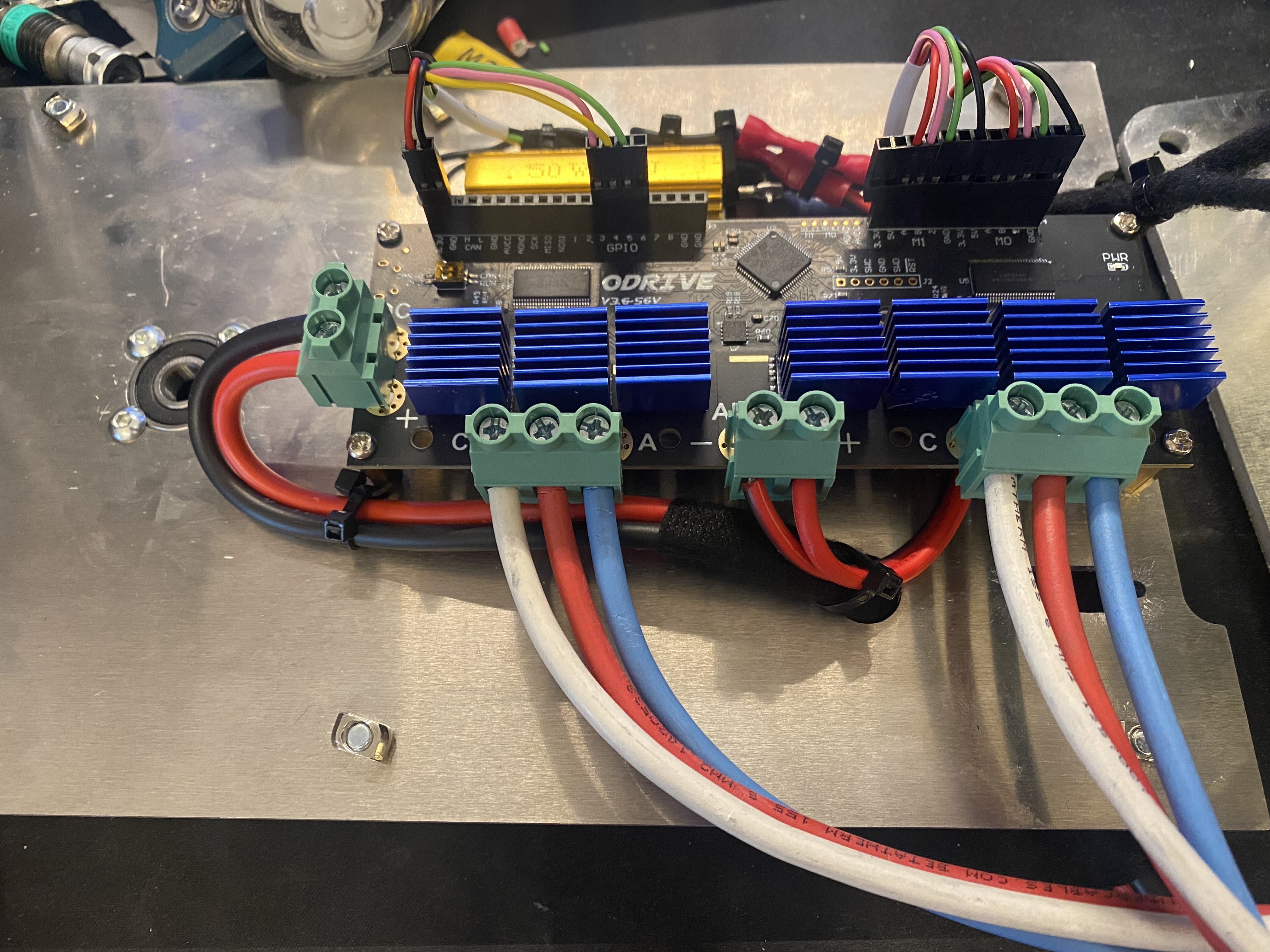
Here you can see the final wiring for the ODrive, including the joystick connection and motor connections. It is important to also attach the USB Cable beforere assembling the unit. Otherwise, it will be very difficult to get to the connector. I’d also recommend to add an USB Isolator. It is not necessary but it will protect your pc in case of some failure and wont send +12V directly into your USB port. Trust me, you don’t want that to happen.
Step 4: Flash the ODrive firmware
Before assembling the Unit, you should install the FFBeast Firmware to the ODrive. In order to do this, you have to use the small switch on the top left to set it into DFU (Device Firmware Upgrade) mode. This switch will be inaccessible when the unit is assembled or at least very, very difficult to reach.
When I connected the ODrive to the USB Port, nothing happened. I was a bit afraid that I damaged it but it turned out that it does not power from USB. It needs to be powered directly. You can hook up the power supply or use a bench power supply like I did to upload the firmware.
To install the new Firmware, you need the STM32CubeProgrammer software. Getting this software is a pain because ST wants to collect all your data… you can use something like 10minute mail to protect your identity. I’d recommend not to support such behavior and keep your data secure. Once you managed to get the programmer software, you can update the firmware. Make sure to follow the Instructions on the FFBeast homepage. After that, you should be able to connect to the controller using the FFBeast Setup App.
Step 5: Assembly
Next step was to assemble the Unit.
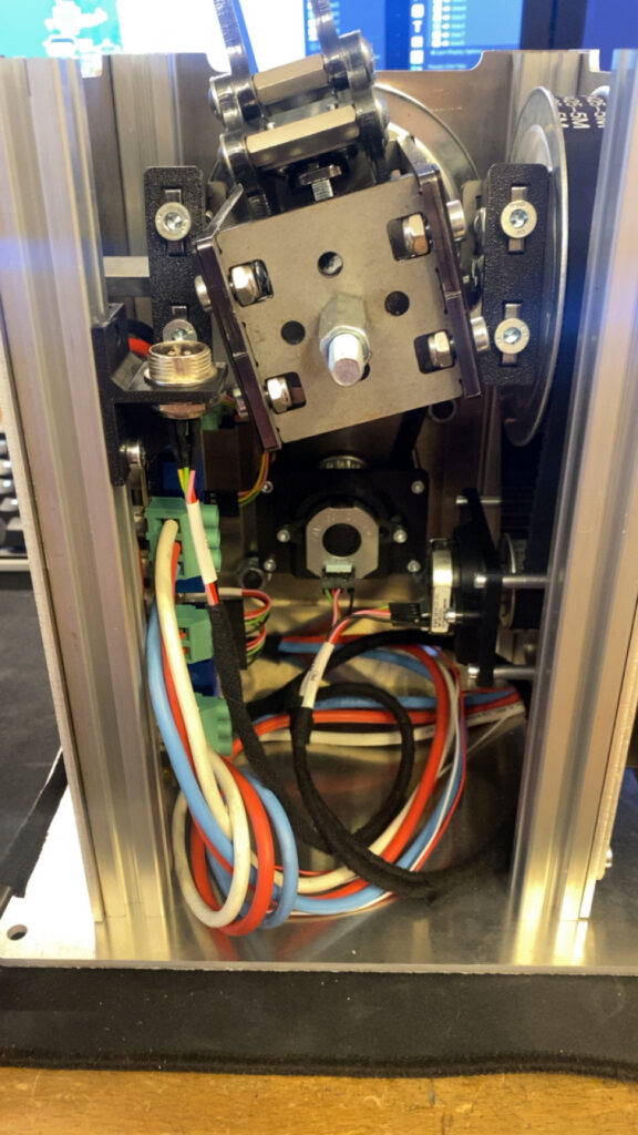
Here is the almost fully assembled unit. As you can see, I’ve added an GX Socket on the top left to the joystick button cable. This allows me to quickly change the stick if i want to.
Step 6: Wire up the electronics Pt.2 (Power Supply)
⚠ Warning ⚠
This project involves working with mains voltage (230 V), which is extremely dangerous and can cause serious injury or death if handled improperly. Only attempt mains wiring if you are experienced, confident, and knowledgeable about electrical safety. Always disconnect power before making modifications, use properly rated components, follow local electrical regulations, and consider consulting a licensed electrician. The author is not responsible for any damage, injury, or accidents resulting from improper use or assembly.
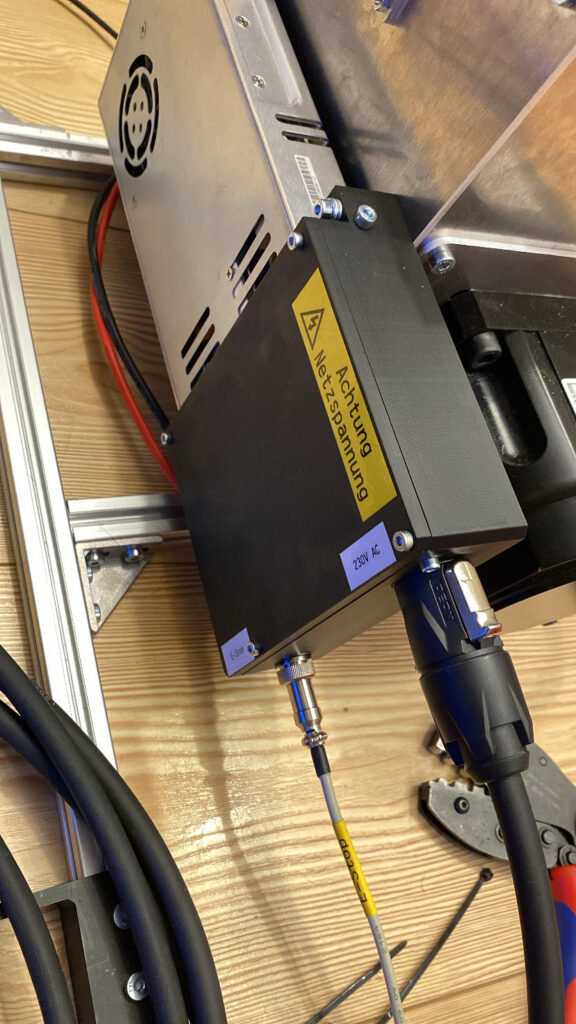
I decided to mount the PSU to the side of the unit. To prevent me from getting shocked or killed by mains voltage, I designed a small 3d printed casing. This casing contains the mains connection, a relay and a connector for the emergency stop button.
Preperations for E-Stop switch
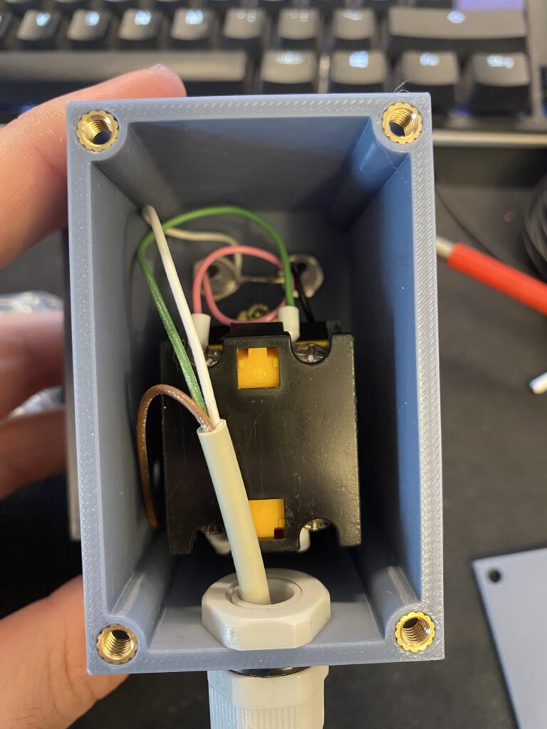
I wanted to add an emergency stop button in case the joystick starts glitching and tries to destroy itself (or me). Since most E-Stop buttons are not rated for over 20 Amps, i needed a different solution. Many people added the e-stop to the primary side and just cut the mains power to the PSU. This would have been the easiest solution. I had some car relays laying around that are rated for 30-40 Amps. I used one of those to cut the power to the ODrive. This allowed me to sue much thinner cable to hook up the button. This also meant that I had to work less with 230V which I really appreciated.
Finally I added a 3 Amp fuse to protect the relay, switch and the correspondent wiring from burning in case of a short.
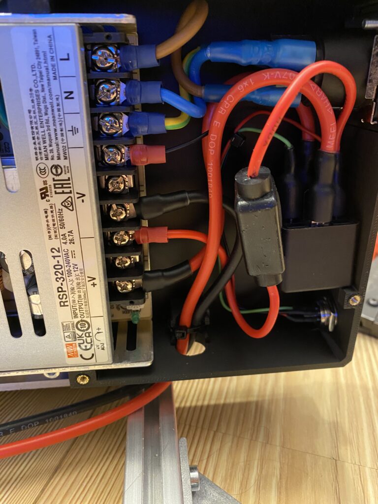
All connections are properly crimped and sealed with heatshrink tubing. The power connector is a Neutrik True1 connector. I really like those and use them on almost all of my projects.
The E-Stop button can be disconnected. Thats what the small GX Socket on the button is for.
Last but not least, I added a cover with a warning for my future self!
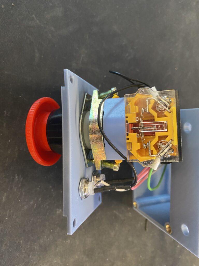
Step 7: Wire up the electronics Pt.3 (Emergency Stop Button)
The E-Stop button is contained in another custom 3d printed enclosure. It contains 2 LEDs. One for indicating +12V on the PSU and one to notify me, that the E-Stop is engaged.
Step 8: Final configuration
The last step before the first test was to configure the ODrive board using the FFBeast Setup App. One issue I had was to figure out how many poles my servos have. To do this, I removed the back plate of the motor.
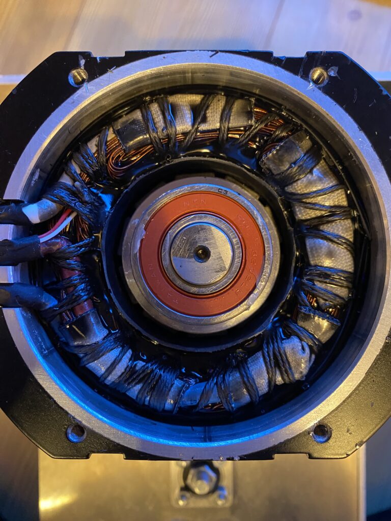
I then counted the magnets and divided that by 2. This gave me the number of poles: 5. After entering the correct amount of poles, all jitter and cogging was gone. I kept the CPR at the default setting.
I raised the powerlimit to 90%. I’d recommend to keep the calibration magnitude as low as possible. It will draw a lot of current. In my case, it drew over 26 Amps during initialization. This caused the PSU to shut off. The only way to get out of that cycle was to flash the firmware again and start from scratch.
Don’t forget to set the Max force available for each axis. The lower you go, the stronger it will be. I did not measure it yet but I will once the joystick is complete.
Lessons learned.
During this project, I picked up some critical lessons — if I’d known them earlier, I could have saved a lot of time and money:
- Double-check parts and BOM. Make sure you are using the right BOM for the version you ordered.
- Follow the Instructions on the website! If you skip steps, you might have to disassemble and redo parts of the joystick. The assembly order matters.
- Be patient. Wait until all parts have arrived before starting the build.
- Slowly adjust settings. Rushing adjustments can cause issues and may require reflashing the ODrive.
Next steps
The next step is to build the joystick arm, wire everything up, and add some finishing touches. I’ll share the progress and updates in the next post.
In the meantime, feel free to ask any questions or share your thoughts in the comments below!