Z80 and I2C
In a previous post, I’ve already presented the MIO card. This card is responsible for :
- PS/2 (Keyboard and mouse via VT82C42)
- IRQs that are not compatible with IM2
- RTC (DS1307, connected to I2C bus)
- Buzzer
- AM9511A APU
- I2C Bus controller
I already tested some of the functionalities including the PCF8584 I2C Bud Controller and was able to get something out of it. However, I have not yet been able to communicate with the I2C. For an upcoming project I need to communicate with an S1531. This IC generates 3 different programmable clock frequencies and communicates over I2C.
Because of this, I had to get the I2C bus working.
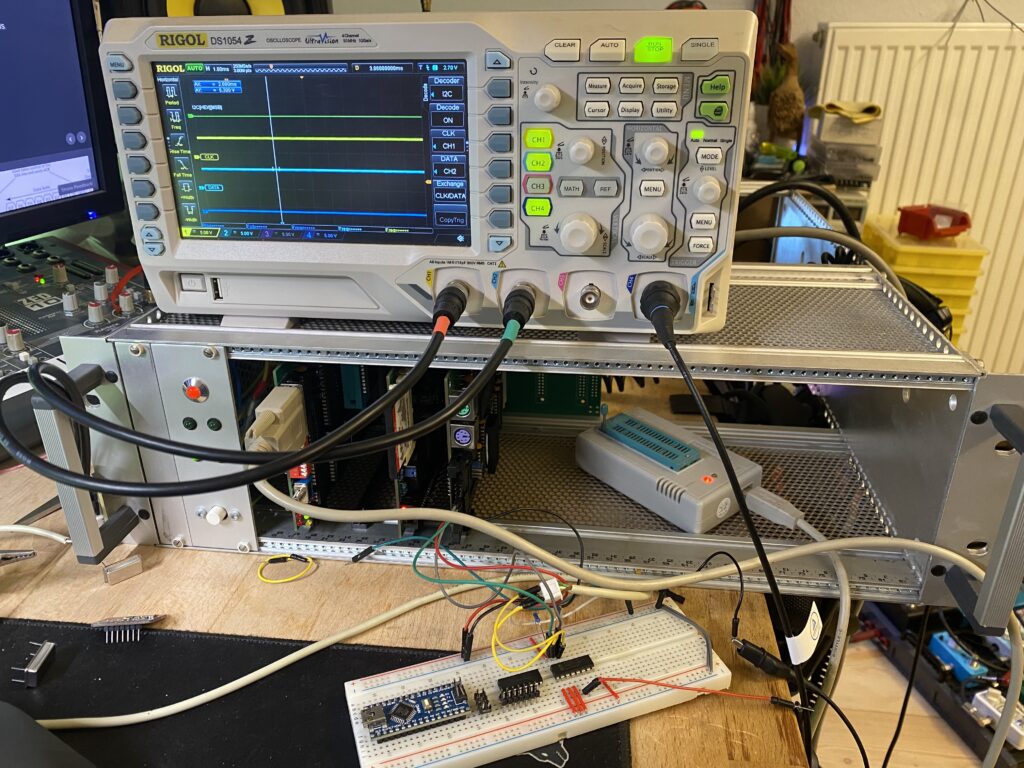
Test Setup
For testing, I used to front panel connector on the MIO card. It gives access to the I2C bus as well as 8 GPIO pins, connected to the Z80 PIO.
I connected the I2C bus to a breadboard with an PCF 8574 I2C I/O expander. I decided to use this IC because it is simple to program and therefor simple to test if the communication is actually working. Along with the PCF8574, I connected my Rigol DS1054 Scope to analyze and debug the I2C bus.
Trying to make the PCF8584 operational
My original idea was to use a dedicated I2C bus controller to reduce CPU utilization and allowing to transmit while the cpu continues with other tasks. This could be achived by utilizing the PCF8584s interrupt feature. I was not aware of how tricky it is to integrate it into the Z80 bus and how slow the device actually is. I would need large delays between the I/O operations with my CPU running at 6MHz.
When I finally managed to properly reset and initialize the PCF8584, it was not able to reliable detect whether the bus is busy or not. Also, I was not able to reliably send data over the bus. Most of the time it did not respond at all and if it did, it sent the wrong data. I was not able to find the issue after days of troubleshooting, re-reading the datasheet and searching through forums.
I tried to:
- Change to CLK and pre-scaler registers -> no success
- Chenge the CPU CLK to 4MHz -> no success
- Wire the RESET line to the PIO to generate a long enough signal -> some success
- Insert additional waitstates -> some success
- Wire /WR signal to PLD to enforce 8080 bus-mode -> no success
- Remove al I2C devices from bus -> no success
- Swap PCF8584 -> no success
I finally decided, that this approach is not worth the time I had already spent and that I have to find a different solution.
Bit-banging the I2C bus
I finally decided to let the CPU handle the I2C communication via the PIO. I used the 2 Pins PA0 and PA1, which were previously used for the PCF8584 IRQ and IACK (later RESET) signals for SCL and SDA.
PA0 is now SDA, and PA1 is now SCL. I’ve implemented the basic routines for reading and writing data from the bus and was able to get an ACK form the PCF8574 and later to successfully control the I/O ports on the PCF8574.
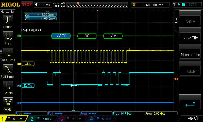
After some code optimizations and removing any additional delays, I was able to increase the SCL frequency to a reasonable speed. There is some room for improvement but for now, this is fast enough.
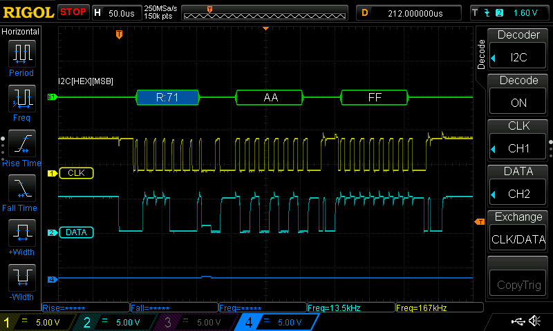
Now i have 2 functions to read and write to any I2C device fast enough and mostly reliable. The SI1531 had some issues with the start-bit. After inserting two NOPs after between the start bit and the first data bit, it responded with an ACK.
At this point, I have a working I2C bus that can be used to interface the S15351 and the RTC.
The I2C driver:
;----------------------------------------------------------------;BIOS Driver for I2C Protocol (Software);by Dennis Gunia (01/2024);; SCL is connected to PA1 of PIO (U6) with pull-up; SDA is connected to PA0 of PIO (U6) with pull-up;----------------------------------------------------------------;================================================================; I/O registers;================================================================;================================================================; I/O pins;================================================================ IIC_CLK .EQU 00000001b IIC_DATA .EQU 00000010b;================================================================; basic access functions ;================================================================;HL contains buffer location;B defines amount of bytes to send;C contains device addressiic_send_buffer: CALL iic_send_sbit ;Send startbit LD A,C AND 0xFE ;Mask R/W bit (must be 0 for write) CALL iic_send_byte ;Send Address CALL iic_read_ack OR A ; if no ack, error JP NZ, iic_send_buffer_erriic_send_buffer_loop; LD A,(HL) INC HL CALL iic_send_byte CALL iic_read_ack OR A ; if no ack, error JP NZ, iic_send_buffer_err DJNZ iic_send_buffer_loop ;loop for remaining bytesiic_send_buffer_done: CALL iic_send_ebit LD A,0 RETiic_send_buffer_err: CALL iic_send_ebit LD A,1 RET;HL contains buffer location;B defines amount of bytes to send;C contains device addressiic_receive_buffer: DEC B CALL iic_send_sbit ;Send startbit LD A,C OR 0x01 ;set R/W bit (must be 1 for read) CALL iic_send_byte ;Send Address CALL iic_read_ack OR A ; if no ack, error JP NZ, iic_receive_buffer_erriic_receive_buffer_loop: CALL iic_receive_byte LD (HL),A INC HL CALL iic_send_ack DJNZ iic_receive_buffer_loop ; last time: CALL iic_receive_byte LD (HL),A INC HL CALL iic_send_nackiic_receive_buffer_done: CALL iic_send_ebit LD A,0 RETiic_receive_buffer_err: CALL iic_send_ebit LD A,1 RET;================================================================; I/O access functions ;================================================================;Reset PIO configurationiic_init: ;SCL HIGH, SDA HIGH LD A,0x03 OUT (CS_PIO_AD), A ;Set port to controll mode (MODE3) LD A,0xCF OUT (CS_PIO_AC), A ;Set inputs/outputs LD A,0xF0 OUT (CS_PIO_AC), A RET; send start bitiic_send_sbit: ;SCL HIGH, SDA HIGH LD A,0x03 OUT (CS_PIO_AD), A ;Set port to controll mode (MODE3) LD A,0xCF OUT (CS_PIO_AC), A ;Set inputs/outputs (SDA and SCL is now output) LD A,0xFC OUT (CS_PIO_AC), A ;SCL HIGH, SDA LOW LD A,0x02 OUT (CS_PIO_AD), A NOP NOP LD A,0x00 OUT (CS_PIO_AD), A NOP NOP RET; send end/stop bitiic_send_ebit: ;Set port to controll mode (MODE3) LD A,0xCF OUT (CS_PIO_AC), A ;Set inputs/outputs (SDA and SCL is now output) LD A,0xFC OUT (CS_PIO_AC), A ;SCL HIGH, SDA LOW LD A,0x02 OUT (CS_PIO_AD), A NOP NOP LD A,0x03 ; both high OUT (CS_PIO_AD), A NOP NOP ;release bus ;Set port to controll mode (MODE3) LD A,0xCF OUT (CS_PIO_AC), A NOP NOP ;Set inputs/outputs (SDA and SCL is now input, sound enabled) LD A,11110111b OUT (CS_PIO_AC), A NOP NOP RETiic_read_ack: LD A,0xCF OUT (CS_PIO_AC), A ;Set inputs/outputs (SCL is now output, SDA input) LD A,0xFD OUT (CS_PIO_AC), A NOP NOP LD A,0x00 ;set SCL LOW OUT (CS_PIO_AD), A NOP NOP XOR 0x02 ;set SCL HIGH OUT (CS_PIO_AD), A NOP IN A,(CS_PIO_AD) ; Read SDA NOP NOP PUSH AF AND 0xFE ; Filter input XOR 0x02 ;set SCL LOW OUT (CS_PIO_AD), A NOP NOP POP AF AND 1 RETiic_send_ack: ;Set port to controll mode (MODE3) LD A,0xCF OUT (CS_PIO_AC), A ;Set inputs/outputs (SDA and SCL is now output) LD A,0xFC OUT (CS_PIO_AC), A NOP NOP LD A,0x00 ; SCL LOW, SDA LOW OUT (CS_PIO_AD), A NOP NOP LD A,0x02 ; SCL HIGH, SDA LOW OUT (CS_PIO_AD), A NOP NOP LD A,0x00 ; SCL LOW, SDA LOW OUT (CS_PIO_AD), A NOP NOP RETiic_send_nack: ;Set port to controll mode (MODE3) LD A,0xCF OUT (CS_PIO_AC), A ;Set inputs/outputs (SDA and SCL is now output) LD A,0xFC OUT (CS_PIO_AC), A NOP NOP LD A,0x02 ; SCL LOW, SDA HIGH OUT (CS_PIO_AD), A NOP NOP LD A,0x03 ; both high OUT (CS_PIO_AD), A NOP NOP LD A,0x02 ; SCL LOW, SDA HIGH OUT (CS_PIO_AD), A NOP NOP RET;A contains byteiic_send_byte: PUSH BC LD C,A ;buffer ;Set port to controll mode (MODE3) LD A,0xCF OUT (CS_PIO_AC), A ;Set inputs/outputs (SDA and SCL is now output) LD A,0xFC OUT (CS_PIO_AC), A LD B,8 ;bit counter iic_send_byte_loop: ;prepare data RL C LD A,0 RLA ; set SCA bit from carry, SCL LOW OUT (CS_PIO_AD), A NOP NOP XOR 0x02 ;set SCL HIGH OUT (CS_PIO_AD), A NOP NOP XOR 0x02 ;set SCL LOW OUT (CS_PIO_AD), A NOP NOP DJNZ iic_send_byte_loop ;loop until counter is 0 ;transmittion end / end loop LD A,C POP BC RETiic_receive_byte: PUSH BC ;Set port to controll mode (MODE3) LD A,0xCF OUT (CS_PIO_AC), A ;Set inputs/outputs (SCL is now output, SDA input) LD A,0xFD OUT (CS_PIO_AC), A LD B,8 ;bit counter LD C,0iic_receive_byte_loop: XOR A ;set SCL LOW OUT (CS_PIO_AD), A NOP NOP LD A,2 ;set SCL HIGH OUT (CS_PIO_AD), A NOP IN A, (CS_PIO_AD) NOP RRA ;read SDA bit RL C ;store bit XOR A ;set SCL LOW again OUT (CS_PIO_AD), A NOP NOP DJNZ iic_receive_byte_loop LD A,C POP BC RET
Leave a Reply