If you have not read my article about my CPU Card, I would recommnend to do it now before you continue reading this article.
As my Z80 Homebrew Computer continues, I intend to add more features to my Z80 computer. Since the CPU board is fairly limited connection wise with only 2 serial ports, I needed to add more I/O options.
PS/2 Connectivity
One majore requirement was to get at least one PS/2 port for keyboard connection. My first prototype used bit-banging over a PIO. This worked but prooved to be very limited due to its very CPU-intensive subroutines. To solve this problem, I took a look at other computers from that area. Most of the homebrew computers used some sot of directly connected keyboard without a dedicated controller and scanned its matrix using parallel ports (e.g. MOS6522, Z80PIO, etc.). Unfortunatley, this solution does not apply here.
PS/2 uses a serial protocol which heavily relies on timing. Doing this only with a parallel port is definetely possible but very unpractical, as my old prototype confirms. So I bgean looking into the direction from which the PS/2 protocol comes from: IBM PC. Or in this case the more period accurate IBM PC/AT. The IBM used a parallel interfaced microcontroller to talk to the AT-Keyboard, the predecessor of the PS/2 keyboard. The Controller used was the Intel 8042. Since the 8042 is not a ready available keyboard controller, it needs programming. I don’t have a programmer to do this. Also, unprogrammed 8042s are hard to get hold of and preprogrammed ICs are rare. Fortunately, other manufacturers provide compatible or even imporved versions of the keyboard controller.
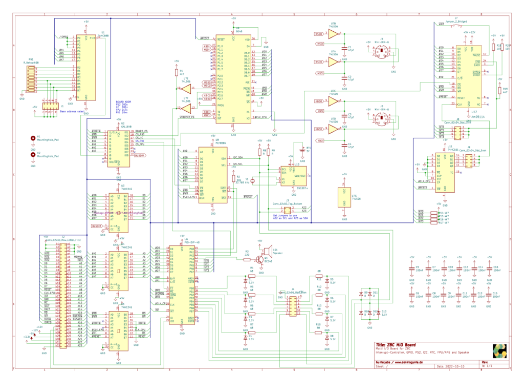
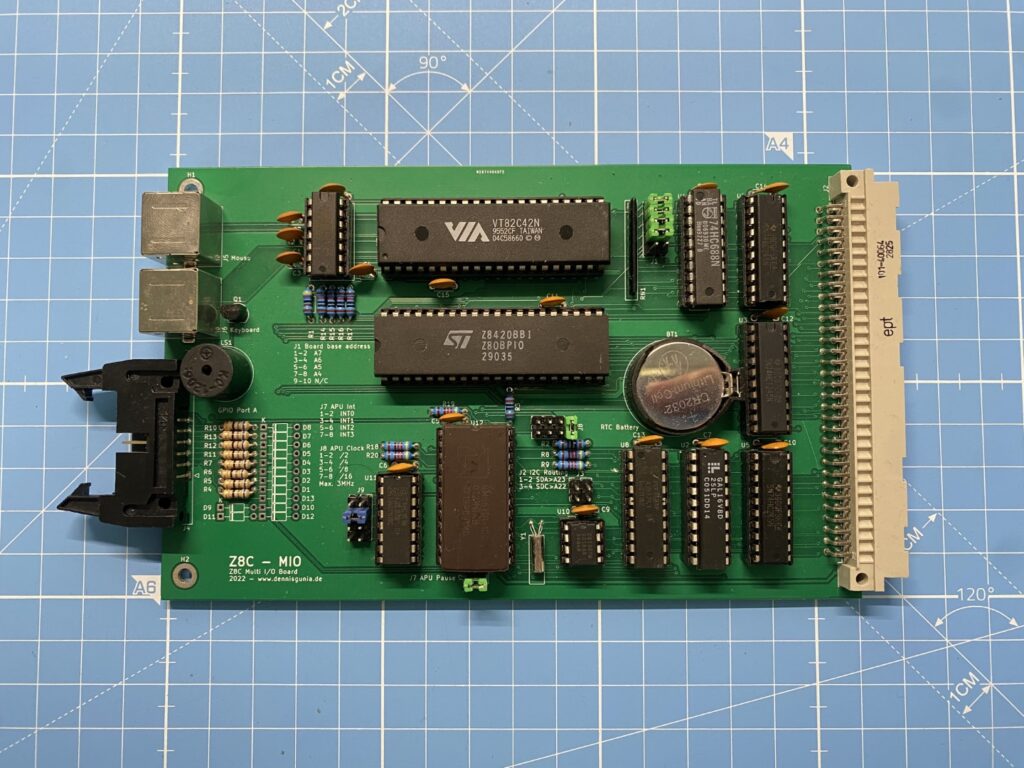
The IC I went for is the VIA VT82C42. It is compatible to the 8042, provides an additional PS/2 Mouse support and can be directly interfaced to the Z80 CPU. Although these chips are as well out of production, they can still be fairly easily sourced form ebay.
The PS/2 Interface is only partially working. I accidentially made a mistake preparing the Mini-DIN socket footprint in KiCad which resulted i the pins being in reverse order. This made some bodges necessary. Now the Keyboard connector is working. The CPU can tolk to the V82C42, initialize it and sned commands to the keyboard. I’ve not yet adapted the monitor to make use of it.
I’ve added the required routines to the ROM. You can find the assembly files on GitHub: https://github.com/dennis9819/Z8C-Homebrew-Computer/blob/master/OperatingSystem/monitor_v2/include/vt82c42.s
I2C Bus Controller
To Interface more modern devices, like RTCs and Programmable Oscillators which will be requiredfor the planned sound interface card, I needed an I2C bus. I wanted to use a dedicated controller because software I2C would take too many of the already limited CPU rescources. The controller i went for is the PCF8584. Although it is not period correct, it was available in 1997 and allows me to direclty and efficiently acces I2C devices from the CPU.
I’ve added the required software routines to the system ROM:
RTC
The Z80 Computer uses an I2C real time clock. The specific type is DS1307.
It is not used in software yet.
APU
To accelerate floating-point operations, I wanted to add some sort of acceleration to the CPU. To stay at least somewhat period correct, the AM9511A Arithmetic Processing Unit (APU) looked like a good choice.
The timing of the AM9511 is difficult for the Z80. The maximum supported bus speed is as far as I know 3MHz. My system however uses at least 4-6MHz. This is almost double the supported bus speed. To solve this, I tried to add waitstates to compensate the slow interface of the APU. I added a 74HC161 with some jumpers to be able to change the APU Clock as well as a jumper for enabling wait-states. This however proved not to be enough and I am not able to access the APU.
It will be removed in a future revision of the PCB and I’m still looking for a better replacement.
Interrupts
My System uses the Z80 Interrupt mode IM2. This is the moste performant mode available on the Z80 and allows for easy implementation with the Z80 PIO, SIO ans CTC. Other Chips that don’t use the Z80 IM2 interrupts are more difficult to integrate. To solve this issue, I decided to use one Port of a Z80 PIO (Programmable Input/Output) to work as a sort of Interrupt controller. The PIO can be programmed to emitt an Interrput when one of the input pins changes state. I used this feature and connected the INT lines form the non-supported devices (like AM8911, CT82C42 and PCF8584).
Additional IO
The rest of the IO pins, not used for Interrupts are connected to an 8-bit parallel I/O ubterface and a small speaker. The speaker can be used to play sounds. The I/O interface is bidirectional and general-purpose.
Adressing / Bus-interface
Each Z80 Computer module needs to interface with the CPU-Bus. Beacuse of the limited current ratings of the Z80s Addres and Data lines, each module contains a buffer for all address, data and controll-lines.
Each module has a 74HC688N comparator to decode the base adress of the module and generate a Module-Selected signal. This signal is then passed onto further decoding logic. In this case a GAL16V8D Programmable Array Logic. This device then generates the specific CE,WR and RD signals for the connected ICs.
Further tasks
Although the board is already in a good state, some work still needs to be done:
- Getting the PS/2 mouse to work
- Implementing software routines to read the RTC
- Adding keyboard input for monitor
Schematics